
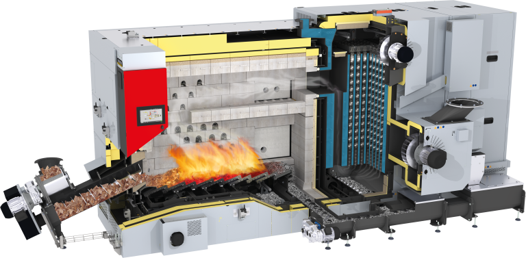
Air intake through the thermally insulated outer shell for combustion air preheating (= adiabatic combustion chamber)
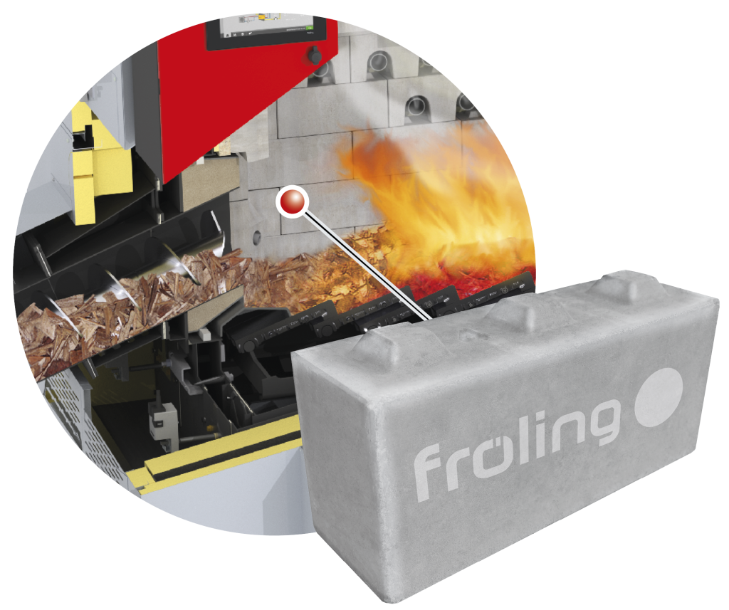
High temperature combustion zone
This increases efficiency even further, particularly with poor quality fuels.
Vertical 3-pass heat exchanger with integrated efficiency optimisation system (WOS) with automatic cleaning function. Operating pressure 6 bar (8 bar on request).
High-temperature flue gas recirculation
FGR
Optimises the results of the combustion process (output, emissions, etc.) for particularly demanding fuels such as pellets, shavings, etc.
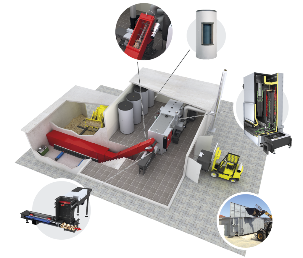
Combined electrostatic precipitator - EFZ multicyclone unit
Combination of electric filter and multicyclone separator for guaranteed very low emission values.
Speed-controlled and monitored induced draught fan, Optionally integrated at three positions directly on the boiler. Can also be installed flexibly at an external position.
Bypass flap for optimised partial load operation and flue gas temperature control.
Collective ash removal from the combustion
chamber and fly ash
Self-contained or for connection to further centralised ash removal system.
Generously dimensioned grate ash screw
Large combustion chamber doors on both sides
Actuated moving grate
Split primary air zone
Automatic ignition
Optional second ignition fan can be fitted for fuels of materials that are difficult to light (due for instance to high water content).
High-temperature combustion chamber with 4-layer jacket, for optimum combustion even with low-quality fuel (e.g. high water content, ...) or alternative fuels. Internal structure: innovative module components made of high-temperature-resistant silicon carbide / first thermal insulation / air jacket / second thermal insulation.
Stoker kit with large-volume,
2-chamber rotary valve with low
installation height
Air-cooled slide-on duct which guarantees minimal energy consumption in the fuel feed-in area and full flexibility for variations in the size of pieces of fuel. The drive gearbox unit to industrial standards is durable, which results in useful pre-drying of the heating material, particularly for fuels with a higher moisture content.
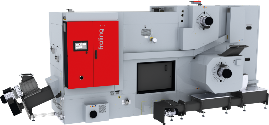
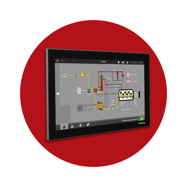
Industrial PLC with 10,1“ glass touch display for easy and intuitive operation
PLC control cabinet
Mounted on the boiler and pre-wired to the electrical components installed on the boiler.
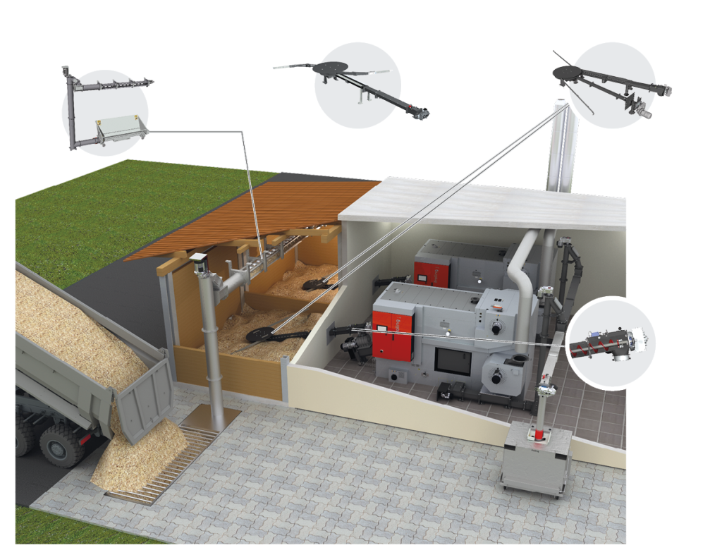
BFSV-H vertical feed screw bunker filling system
FBR-G with separate rotary agitator
FBR-G with separate rotary agitator
GAR-G system with separate rotary agitator
Progressive metering screw with modular plug-in system
The progressive feed screw guarantees reliable fuel transport. Thanks to the progressive screw pitch, the material does not become compacted and can always be transported easily. This ensures less force and energy consumption. The modular design of the feed screw with standard extension pieces between 100 and 2,000 mm (increments of 100/200 mm) allows easy assembly and flexible positioning of the system in the boiler room. The Froling feed screw does not require sloping sides.
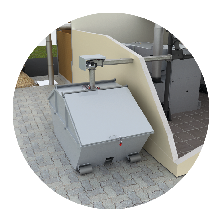
Flap-bottomed container (galvanised for exterior installation)
The ash is automatically conveyed into the flap-bottomed container whence it can easily be emptied. This ensures long emptying intervals and maximum convenience. Available in sizes 330, 500 or 1000 ltr.
Suitable for coarse wood chips P63 (previously G100)
Depending on the application, raking chain conveyors, conveyor belts or hydraulic cross feeders may be used, with the option of connection of sprinklers.
Fröling storage tank systems with sensor strip
Fröling storage tank systems are available in various sizes and are also ideal for combining with other energy systems.
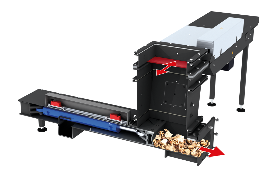
Hydraulic loading
The burn back slide valve closes off the fuel feed-in from the fuel store compartment. The fuel is fed into the combustion chamber directly on to the moving grate by means of a hydraulic ram. Available from TMe 350 kW. For coarse fuels up to P63 (formerly G 100).
EFZ 350-550 kW electrostatic precipitator cyclone
The modular electrostatic precipitator system combines the function of electrostatic charging of dust particles and the centrifugal separation of a multicyclone to reduce fine dust emissions.
Sliding floor discharge unit
The sliding floor discharge unit is used to discharge combustion materials from a rectangular or square bunker. The sliding floor discharge system can be equipped with one or more slide rods and is installed on the flat floor of the bunker.