WOOD CHIP and shavings heating system
800 – 1200 kW
- Sturdy design
- Industrial version

Wood chip and shavings heating system
NEW! LMe
The LMe from Fröling is a future-oriented heating system for the fully automatic use of a wide range of biomass fuels. With the LMe, Froling ensures a robust design, modular components and easy access for maintenance. The result is a heating system that delivers impressive reliability, efficiency and technological maturity in day-to-day operation.
Equipped with a hydraulically driven moving grate, the fuel is continuously conveyed through the high-temperature combustion chamber. This ensures complete combustion and thus maximum efficiency. We support heat generation through an intelligent control system that continuously monitors and dynamically adjusts all relevant parameters.
The LMe is characterised by a high degree of automation. All central processes, from transport of material to removal of ash, run fully automatically, enabling low-maintenance continuous operation even under demanding conditions.

Information/advice
You would like to have further product information or you have general questions regarding our company?
The latest technology

Controllable boiler bypass
For optimised partial load operation and flue gas temperature control
Tertiary air vents
for increased efficiency in the combustion process.
Integrated cyclone separator
Multi-cyclone separator with central ash removal for guaranteed lowest emission values.
Automatic ignition
Two automatic ignitions ensure quick and efficient ignition of the heating material. With hydraulic loading, a third ignition fan can optionally be installed in the slide-in area.
Hydraulische Beschickung
The burn back slide valve closes off the fuel feed-in from the fuel store compartment. The fuel is fed into the combustion chamber directly on to the moving grate by means of a hydraulic ram.
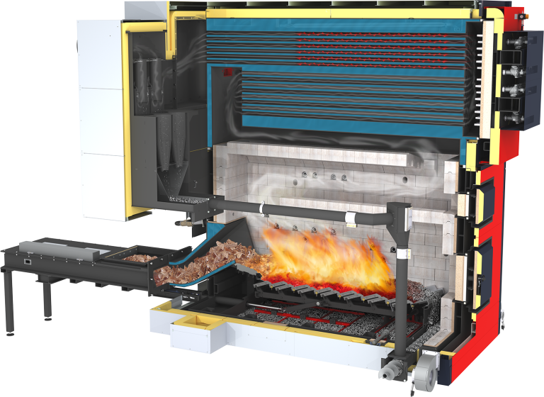
High-temperature combustion chamber with 4-layer jacket
For optimum combustion even with low-quality fuel (e.g. high water content, ...) or alternative fuels. Internal structure: innovative module components of high-temperature-resistant silicon carbide / first thermal insulation / air jacket / second thermal insulation.
Multiple-pass heat exchanger
With generously dimensioned heat exchanger surfaces. In addition, the turbulators in the heat exchanger pipes ensure the lowest flue gas temperatures and thus even higher efficiency. Operating pressure 6 bar (8 bar on request).
Compressed air cleaning system
With direct flow to each heat exchanger pipe and integrated, space-saving compressed air tanks.
High temperature after-burning zone
This increases efficiency even further, particularly with poor quality fuels.
Modular components of silicon carbide
Complete combustion chamber lining with highquality module components of silicon carbide.
Secondary air openings
These ensure optimum combustion and complete burn-through.
Hydraulically actuated moving grate
Ensures continuous transport of fuel and complete burnthrough (even with difficult types of fuel). The moving
grate is capable of continuous operation.
Systematic convenience
The PLC 4000 controller is built using high-quality industry-standard components. The clear, user-friendly control system offers a wide range of different settings and visualisation options for individual, efficient and stable operation. The Froling PLC 4000 offers numerous functional options such as multi-sensor storage tank management, heating circuit and network temperature control, external output specifications, cascade function, integration, monitoring and control of additional peripheral components.
Advantages
Powerful PLC controller with big colour touch display
Simple and reliable remote access via Froling visualisation software
Numerous functional options


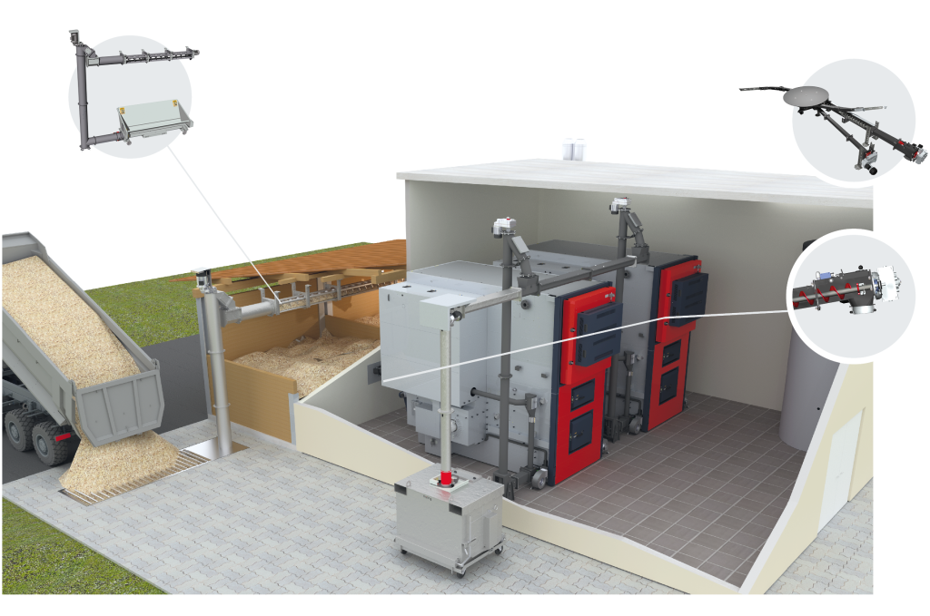
Vertical feed screw BFSV-H bunker filling system
GAR-G system with separate rotary agitator (NEW: ∅300)
Sturdy articulated arm discharge unit for coarse grain fuels and for fuels with a low
propensity to trickle. Torsion-resistant industrial quality ensues a long working life and
optimum discharge.
Progressive metering screw with modular plug-in system
The progressive feed screw guarantees reliable fuel transport. Thanks to the progressive screw pitch, the material does not become compacted and can always be transported easily. This ensures less force and energy consumption. The modular design of the feed screw with standard extension pieces between 100 and 2,000 mm (increments of 100/200 mm) allows easy assembly and flexible positioning of the system in the boiler room. The Froling feed screw does not require sloping sides.
Flap-bottomed container (galvanised for exterior installation)
The ash is automatically conveyed into the flap-bottomed container whence it can easily be emptied. This ensures long emptying intervals and maximum convenience.

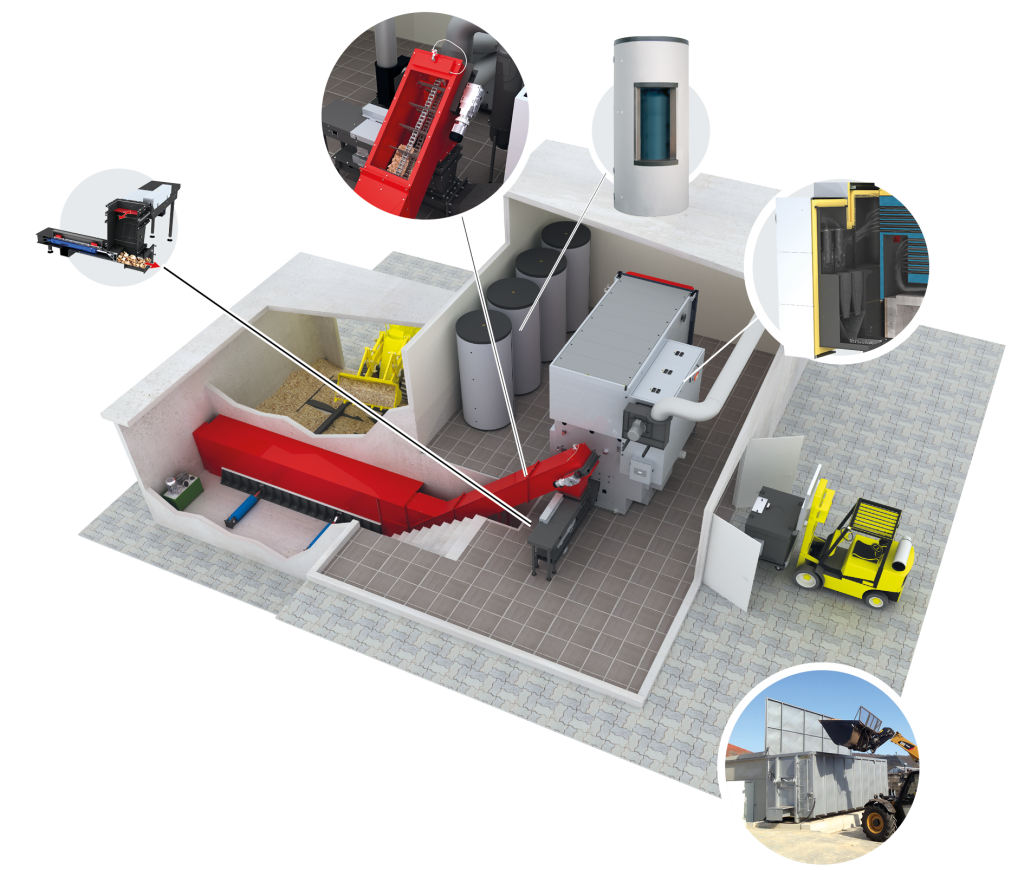
Brennstofffördereinrichtung für Grobhackgut P63 (ehemals G100)
Depending on the application, raking chain conveyors, conveyor belts or hydraulic
cross feeders may be used, with the option of connection of sprinklers.
Froling storage tank systems with sensor strip
Fröling storage tank systems are available in various sizes and are also ideal for combining with other energy systems.
Burn back slide valve (RBS)
Hydraulic fuel feed-in
Integrated cyclone separator
The multi-cyclone separator reduces fine dust emissions to a
minimum.
Alternatively an interchangeable sliding floor container can be used
Example
Discharge: SB container
Fuel: Wood chips
Brochures / EU Label
Technical specifications
| Technical specifications - LMe | 800 | 900 | 1000 | 1100 | 1200 |
|---|---|---|---|---|---|
| Rated heat output [kW] | 799 | 899 | 999 | 1099 | 1199 |
| Output range [kW] | 239,7-799 | 269,7-899 | 299,7-999 | 329,7-1099 | 359,7-1199 |
| Rated thermal input of fuel with pellets [kW] | 826,3 | 934,5 | 1045 | 1144,8 | 1245 |
| Rated thermal input of fuel with wood chips [kW] | 831,4 | 940,4 | 1045 | 1144,8 | 1245 |
| Nominal output-efficiency wood chips | 96,1 % | 95,6 % | 95,6 % | 96 % | 96,3 % |
| Nominal output efficiency, pellets | 96,7 % | 96,2 % | 96,6 % | 96 % | 96,3 % |
| Electrical connection | 400V / 50Hz / C35A or as shown on the circuit diagram | 400V / 50Hz / C35A or as shown on the circuit diagram | 400V / 50Hz / C35A or as shown on the circuit diagram | 400V / 50Hz / C35A or as shown on the circuit diagram | 400V / 50Hz / C35A or as shown on the circuit diagram |
| Max. permitted operating overpressure [bar] | 6 (8²) | 6 (8²) | 6 (8²) | 6 (8²) | 6 (8²) |
| Total dry weight including attachments. [kg] | 16200 | 16200 | 16200 | 16200 | 16200 |
| Weight - combustion chamber incl. SiC modules [kg] | 9985 | 9985 | 9985 | 9985 | 9985 |
| Weight of SiC modules [kg] | 4610 | 4610 | 4610 | 4610 | 4610 |
| Weight of SiC modules [kg] | 5750 | 5750 | 5750 | 5750 | 5750 |
| Combustion chamber installation dimensions (L x W x H) incl. collision protection and insulating sheet panelling [mm] | 4285 x 1980 x 2200 | 4285 x 1980 x 2200 | 4285 x 1980 x 2200 | 4285 x 1980 x 2200 | 4285 x 1980 x 2200 |
| Dimensions required for heat exchanger installation [mm] (L x B x H) | 4350 x 2270 x 1715 (with return mixer group) 4350 x 1910 x 1715 (without return mixer group) | 4350 x 2270 x 1715 (with return mixer group) 4350 x 1910 x 1715 (without return mixer group) | 4350 x 2270 x 1715 (with return mixer group) 4350 x 1910 x 1715 (without return mixer group) | 4350 x 2270 x 1715 (with return mixer group) 4350 x 1910 x 1715 (without return mixer group) | 4350 x 2270 x 1715 (with return mixer group) 4350 x 1910 x 1715 (without return mixer group) |
| Flue spigot diameter [mm] | 400 | 400 | 400 | 400 | 400 |
| Heat exchanger water capacity [l] | 2390 | 2390 | 2390 | 2390 | 2390 |
| Minimum boiler return temperature [°C] | 70 | 70 | 70 | 70 | 70 |
| Max. permitted operating temperature [°C] | >100³) | >100³) | >100³) | >100³) | >100³) |
| Flue gas temperature (at NL / at PL [°C] | 140 (100) | 140 (100) | 150 (100) | 160 (100) | 160 (100) |
| Permitted fuel as per EN ISO 17225 | Part 4: Wood chips P16s - P45s class A1 + A2 P63 with hydraulic loading Part 2: Wood pellets, D06 / class A1 + A2 | Part 4: Wood chips P16s - P45s class A1 + A2 P63 with hydraulic loading Part 2: Wood pellets, D06 / class A1 + A2 | Part 4: Wood chips P16s - P45s class A1 + A2 P63 with hydraulic loading Part 2: Wood pellets, D06 / class A1 + A2 | Part 4: Wood chips P16s - P45s class A1 + A2 P63 with hydraulic loading Part 2: Wood pellets, D06 / class A1 + A2 | Part 4: Wood chips P16s - P45s class A1 + A2 P63 with hydraulic loading Part 2: Wood pellets, D06 / class A1 + A2 |
2 on request
³ Higher boiler temperatures on request
Dimensions

| All dimensions in mm - LMe | 800 | 900 | 1000 | 1100 | 1200 |
|---|---|---|---|---|---|
| L1 Length of boiler | 4345 | 4345 | 4345 | 4345 | 4345 |
| L2 Swing range of the reversing chamber door | 1195 | 1195 | 1195 | 1195 | 1195 |
| L3 Width of stoker (screw-fed) | 1010 | 1010 | 1010 | 1010 | 1010 |
| L4 Distance between the stoker and the back of the boiler | 510 | 510 | 510 | 510 | 510 |
| L5 Lenght of hydraulic stoker | 2850 | 2850 | 2850 | 2850 | 2850 |
| L6 Distance between the hydraulic stoker connection and the side of boiler | 500 | 500 | 500 | 500 | 500 |
| L7 Distance from the flow to the front of the boiler | 1240 | 1240 | 1240 | 1240 | 1240 |
| L8 Distance from the return to the front of the boiler (with integrated mixing valve group for return temperature control | 1765 | 1765 | 1765 | 1765 | 1765 |
| L9 Distance from the return to the front of the boiler (with on-site return temperature control) | 3415 | 3415 | 3415 | 3415 | 3415 |
| L10 Distance from the flue gas pipe top connection to the front face of the boiler | 4490 | 4490 | 4490 | 4490 | 4490 |
| B1 Overall width of the boiler | 3195 | 3195 | 3195 | 3195 | 3195 |
| B2 Width boiler | 1915 | 1915 | 1915 | 1915 | 1915 |
| B3 Width multicyclone | 875 | 875 | 875 | 875 | 875 |
| H1 Boiler height | 3830 | 3830 | 3830 | 3830 | 3830 |
| H2 Heigth of return connection (with on-site return temperature control) | 3580 | 3580 | 3580 | 3580 | 3580 |
| H3 Heigth of flue gas pipe connection | 3345 | 3345 | 3345 | 3345 | 3345 |
| H4 Heigth of the stoker connection (screw-fed) | 1165 | 1165 | 1165 | 1165 | 1165 |
| H5 Height of the return connection (with integrated mixing valve group for return temperature control) | 3250 | 3250 | 3250 | 3250 | 3250 |
| H6 Height of the flow connection | 3580 | 3580 | 3580 | 3580 | 3580 |
For you personally
Information & advice
You would like to have further product information or you have general questions regarding our company?
